We have our Papilio DUO development environment up and running (I hope), so let’s try to get something simple working. In this post, I’m going to follow Jack Gassett’s “Hello World” video with the walkthrough adapted to my (Ubuntu) environment.
Step 1: Launch DesignLab
Open a terminal and start DesignLab as follows:
DesignLab &
A side note for anyone using a multi-monitor setup like me: if you move any of your DesignLab windows to a different display, weird things will happen and the program will become unusable.
DesignLab will automatically detect the location of ISE. You can confirm this by going to File | Preferences. In the Preferences window, the value of Linux ISE location should be set to /opt/Xilinx/14.7/ISE_DS/ISE/bin/lin64 or wherever your ISE installation is to be found.
Step 2: Create a new project
The video says that the button to create a new project is labelled New Papilio Project. In DesignLab 1.0.8 running on my machine, the equivalent icon is labelled New FPGA Project. This is a file-style icon with a big superimposed plus sign on it:

Once the new window opens, you should be able to close the original DesignLab window.
Save the file using Ctrl+Shift+S and click OK to save the project under the default name New_Blank_Circuit. This will create a directory with location $HOME/New_Blank_Circuit containing an New_Blank_Circuit.ino file. The .ino file is a C/C++ source file containing some boilerplate code which we’ll replace in a later step.
Step 3: Plug the Papilio DUO board in
Note that Jack’s DUO board in the video is black. Mine’s red:
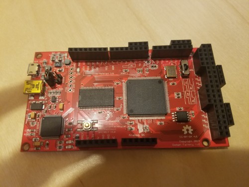
At this point, I separated the Papilio DUO from the Classic Computing Shield (as shown in the photo). I then connected the Papilio DUO board to a free USB port on my laptop using the mini USB connector and mini USB cable. The mini USB port on the board connects directly to the FPGA whereas the micro USB port goes to the Arduino microcontroller. We’ll concentrate on the FPGA side of things to start with.
A red LED lights up!
Step 4: Check that the OS detects the board
The video talks about Device Manager in Windows. On Ubuntu we should, instead, use the terminal:
lsusb
Before plugging in the board, lsusb reports:
Bus 002 Device 002: ID 8087:0024 Intel Corp. Integrated Rate Matching Hub
Bus 002 Device 001: ID 1d6b:0002 Linux Foundation 2.0 root hub
Bus 004 Device 001: ID 1d6b:0003 Linux Foundation 3.0 root hub
Bus 003 Device 001: ID 1d6b:0002 Linux Foundation 2.0 root hub
Bus 001 Device 004: ID 04f2:b217 Chicony Electronics Co., Ltd Lenovo Integrated Camera (0.3MP)
Bus 001 Device 006: ID 0d8c:0005 C-Media Electronics, Inc.
Bus 001 Device 010: ID 09ea:0131
Bus 001 Device 009: ID 045e:000b Microsoft Corp. Natural Keyboard Elite
Bus 001 Device 008: ID 0461:4e22 Primax Electronics, Ltd
Bus 001 Device 007: ID 09ea:0130
Bus 001 Device 005: ID 05e3:0610 Genesys Logic, Inc. 4-port hub
Bus 001 Device 003: ID 17ef:100a Lenovo ThinkPad Mini Dock Plus Series 3
Bus 001 Device 002: ID 8087:0024 Intel Corp. Integrated Rate Matching Hub
Bus 001 Device 001: ID 1d6b:0002 Linux Foundation 2.0 root hub
After plugging in the board, lsusb reports:
Bus 002 Device 002: ID 8087:0024 Intel Corp. Integrated Rate Matching Hub
Bus 002 Device 001: ID 1d6b:0002 Linux Foundation 2.0 root hub
Bus 004 Device 001: ID 1d6b:0003 Linux Foundation 3.0 root hub
Bus 003 Device 001: ID 1d6b:0002 Linux Foundation 2.0 root hub
Bus 001 Device 004: ID 04f2:b217 Chicony Electronics Co., Ltd Lenovo Integrated Camera (0.3MP)
Bus 001 Device 006: ID 0d8c:0005 C-Media Electronics, Inc.
Bus 001 Device 010: ID 09ea:0131
Bus 001 Device 009: ID 045e:000b Microsoft Corp. Natural Keyboard Elite
Bus 001 Device 008: ID 0461:4e22 Primax Electronics, Ltd
Bus 001 Device 007: ID 09ea:0130
Bus 001 Device 005: ID 05e3:0610 Genesys Logic, Inc. 4-port hub
Bus 001 Device 003: ID 17ef:100a Lenovo ThinkPad Mini Dock Plus Series 3
Bus 001 Device 012: ID 0403:7bc0 Future Technology Devices International, Ltd
Bus 001 Device 002: ID 8087:0024 Intel Corp. Integrated Rate Matching Hub
Bus 001 Device 001: ID 1d6b:0002 Linux Foundation 2.0 root hub
From this we can conclude that the Papilio DUO corresponds to the Future Technology Devices International, Ltd entry. From this we can figure out the bus and device number for the board. I don’t know if this will be needed or not.
Alternatively usb-devices yields the following information:
T:  Bus=01 Lev=02 Prnt=02 Port=00 Cnt=01 Dev#= 12 Spd=480 MxCh= 0
D:  Ver= 2.00 Cls=00(>ifc ) Sub=00 Prot=00 MxPS=64 #Cfgs=  1
P:  Vendor=0403 ProdID=7bc0 Rev=07.00
S:  Manufacturer=Gadget Factory
S:  Product=Papilio DUO
S:  SerialNumber=100000000000
C:  #Ifs= 2 Cfg#= 1 Atr=80 MxPwr=100mA
I:  If#= 0 Alt= 0 #EPs= 2 Cls=ff(vend.) Sub=ff Prot=ff Driver=ftdi_sio
I:  If#= 1 Alt= 0 #EPs= 2 Cls=ff(vend.) Sub=ff Prot=ff Driver=ftdi_sio
Step 5: Configure DesignLab to see the board
Set the board type:
- Click on the Tools menu
- Click on the Board submenu
- Click on the Papilio FPGA Boards submenu
- Select Papilio DUO FPGA 2MB - ZPUino
Select the appropriate port:
- Click on the Tools menu
- Click on the Port submenu
- Select /dev/ttyUSB0 (Papilio DUO FPGA)
My system shows an additional port (/dev/ttyUSB1 (Papilio DUO FPGA)). Without any more information, I chose the first one listed.
Step 6: Create a starter sketch
This is Jack Gassett’s example:
Enter this and save it using Ctrl+S.
Step 7: View circuit
Click on the button labelled View Circuit. This is an “eyeball” icon:

This should open up a PDF rendering of the circuit in your default PDF viewer. Jack’s video give a very brief description of what the PDF shows you.
Step 8: Load circuit
Next, we click the Load Circuit button (a icon of the board with an arrow pointing downwards towards it):

In the status pane at the bottom of DesignLab, you’ll eventually see Done burning bitfile. The output I see when I load the circuit is as follows:
/path/to/home/.local/DesignLab-1.0.8/hardware/tools/papilio/papilio_loader
Programming to SPI Flash
Using built-in device list
Programming a Papilio Plus LX9
Using built-in device list
JTAG chainpos: 0 Device IDCODE = 0x24001093	Desc: XC6SLX9

Uploading "bscan_spi_lx9.bit". DNA is 0xb99dd406621820ff
Done.
Programming time 504.1 ms

Programming External Flash Memory with "/path/to/home/.local/DesignLab-1.0.8/libraries/ZPUino_Vanilla/circuit/DUO_LX9/papilio_duo_lx9.bit".
Found Macronix Flash (Pages=32768, Page Size=256 bytes, 67108864 bits).
Erasing    :
Doing Partial Erase
......Ok
Verifying  :
......Pass
Programming :
......Ok
Verifying  :
......Pass
Done.
SPI execution time 15923.7 ms
USB transactions: Write 6855 read 6686 retries 1784
Using built-in device list
JTAG chainpos: 0 Device IDCODE = 0x24001093	Desc: XC6SLX9

ISC_Done       = 0
ISC_Enabled    = 0
House Cleaning = 1
DONE           = 0
Step 9: Modify the sketch
Jack then modifies his sketch to send “Hello World” over the serial port:
Step 10: Upload the sketch
We can then upload this sketch to the device using the Upload button. This is an arrow pointing to the right:

First panic: the compiler spews out many warnings of the following form:
/path/to/home/.local/DesignLab-1.0.8/hardware/zpuino/zpu20/cores/zpuino/start.S:333:7: warning: no newline at end of file
/path/to/home/.local/DesignLab-1.0.8/hardware/zpuino/zpu20/cores/zpuino/crt-c.c:37: warning: unused parameter 'argc'
/path/to/home/.local/DesignLab-1.0.8/hardware/zpuino/zpu20/cores/zpuino/crt-c.c:37: warning: unused parameter 'argv'
/path/to/home/.local/DesignLab-1.0.8/hardware/zpuino/zpu20/cores/zpuino/crt-c.c:5: warning: 'start_brk' defined but not used
/path/to/home/.local/DesignLab-1.0.8/hardware/zpuino/zpu20/cores/zpuino/zstdio.c: In function `fread':
/path/to/home/.local/DesignLab-1.0.8/hardware/zpuino/zpu20/cores/zpuino/zstdio.c:294: warning: comparison of unsigned expression < 0 is always false
/path/to/home/.local/DesignLab-1.0.8/hardware/zpuino/zpu20/cores/zpuino/zstdio.c: At top level:
/path/to/home/.local/DesignLab-1.0.8/hardware/zpuino/zpu20/cores/zpuino/zstdio.c:342: warning: unused parameter 'p'
/path/to/home/.local/DesignLab-1.0.8/hardware/zpuino/zpu20/cores/zpuino/zstdio.c:263: warning: unused parameter 'stream'
/path/to/home/.local/DesignLab-1.0.8/hardware/zpuino/zpu20/cores/zpuino/zstdio.c:263: warning: unused parameter 'pos'
/path/to/home/.local/DesignLab-1.0.8/hardware/zpuino/zpu20/cores/zpuino/zstdio.c:258: warning: unused parameter 'stream'
/path/to/home/.local/DesignLab-1.0.8/hardware/zpuino/zpu20/cores/zpuino/zstdio.c:258: warning: unused parameter 'pos'
/path/to/home/.local/DesignLab-1.0.8/hardware/zpuino/zpu20/cores/zpuino/zstdio.c:254: warning: unused parameter 'stream'
/path/to/home/.local/DesignLab-1.0.8/hardware/zpuino/zpu20/cores/zpuino/zstdio.c:249: warning: unused parameter 'stream'
/path/to/home/.local/DesignLab-1.0.8/hardware/zpuino/zpu20/cores/zpuino/zstdio.c:234: warning: unused parameter 'mode'
/path/to/home/.local/DesignLab-1.0.8/hardware/zpuino/zpu20/cores/zpuino/zstdio.c:218: warning: unused parameter 'mode'
/path/to/home/.local/DesignLab-1.0.8/hardware/zpuino/zpu20/cores/zpuino/zfdevice.c:85: warning: unused parameter 'handle'
/path/to/home/.local/DesignLab-1.0.8/hardware/zpuino/zpu20/cores/zpuino/zfdevice.c:85: warning: unused parameter 'buf'
/path/to/home/.local/DesignLab-1.0.8/hardware/zpuino/zpu20/cores/zpuino/zfdevice.c:89: warning: unused parameter 'handle'
/path/to/home/.local/DesignLab-1.0.8/hardware/zpuino/zpu20/cores/zpuino/zfdevice.c:89: warning: unused parameter 'pos'
/path/to/home/.local/DesignLab-1.0.8/hardware/zpuino/zpu20/cores/zpuino/zfdevice.c:89: warning: unused parameter 'whence'
/path/to/home/.local/DesignLab-1.0.8/hardware/zpuino/zpu20/cores/zpuino/zfdevice.c:67: warning: unused parameter 'handle'
/path/to/home/.local/DesignLab-1.0.8/hardware/zpuino/zpu20/cores/zpuino/HardwareSerial.cpp: In member function `size_t HardwareSerial::writeAndTranslate(const uint8_t*, int)':
/path/to/home/.local/DesignLab-1.0.8/hardware/zpuino/zpu20/cores/zpuino/HardwareSerial.cpp:41: warning: unused variable 's'
/path/to/home/.local/DesignLab-1.0.8/hardware/zpuino/zpu20/cores/zpuino/HardwareSerial.cpp: At global scope:
/path/to/home/.local/DesignLab-1.0.8/hardware/zpuino/zpu20/cores/zpuino/HardwareSerial.cpp:55: warning: unused parameter 'ptr'
/path/to/home/.local/DesignLab-1.0.8/hardware/zpuino/zpu20/cores/zpuino/HardwareSerial.cpp:55: warning: unused parameter 'dest'
/path/to/home/.local/DesignLab-1.0.8/hardware/zpuino/zpu20/cores/zpuino/HardwareSerial.cpp:55: warning: unused parameter 'size'
/path/to/home/.local/DesignLab-1.0.8/hardware/zpuino/zpu20/cores/zpuino/zposix.cpp:258: warning: unused parameter 'fd'
/path/to/home/.local/DesignLab-1.0.8/hardware/zpuino/zpu20/cores/zpuino/zposix.cpp:254: warning: unused parameter 'pathname'
/path/to/home/.local/DesignLab-1.0.8/hardware/zpuino/zpu20/cores/zpuino/zposix.cpp:254: warning: unused parameter 'mode'
/path/to/home/.local/DesignLab-1.0.8/hardware/zpuino/zpu20/cores/zpuino/zposix.cpp:234: warning: unused parameter 'timep'
/path/to/home/.local/DesignLab-1.0.8/hardware/zpuino/zpu20/cores/zpuino/zposix.cpp:215: warning: unused parameter 'err'
/path/to/home/.local/DesignLab-1.0.8/hardware/zpuino/zpu20/cores/zpuino/zpuino.cpp:13: warning: missing initializer for member `interrupt_type_t::arg'
/path/to/home/.local/DesignLab-1.0.8/hardware/zpuino/zpu20/cores/zpuino/zpuino.cpp:31: warning: unused parameter 'mode'
Executing  /path/to/home/.local/DesignLab-1.0.8/hardware/tools/zpu/bin/zpu-elf-size /tmp/build6623424867067206092.tmp/New_Blank_Circuit.cpp.elf
Binary sketch size: 7,832 bytes (of a 2,048,000 byte maximum) - 6,440 bytes ROM, 2,484 bytes memory, 0% used

Sketch uses 5,348 bytes (0%) of program storage space. Maximum is 2,048,000 bytes.
Global variables use 1,092 bytes of dynamic memory.
These warnings look to be benign. The last bit, however, is a problem:
open: No such file or directory
Could not open port, exiting...
I suspect that I chose the wrong serial port in Step 5. So, I went back and selected to /dev/ttyUSB1 (Papilio DUO FPGA) from Tools | Port. I then clicked Upload again.
I got lucky:
Board: Unknown board @ 96000000 Hz (0xb4051300)
Programming completed successfully in 1.73 seconds.
Step 11: Observe the output
At this point, the little green LED marked LED on the DUO board should be flashing: on for a second, off for a second in a loop. We can also fire up the serial monitor to check what’s happening with the serial port by clicking on the Serial Monitor button (a magnifying glass):

And, lo, the monitor on /dev/ttyUSB1 will dutifully print out Hello World once a second!
That gets us to about the 3min57sec mark on Jack’s video. I will pick up from that point next time.